


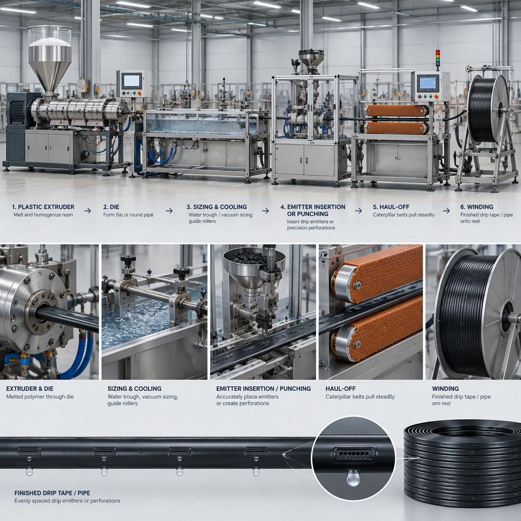
The short answer: haul-off speed is a control point, not a universal recipe
In drip pipe and drip tape production, haul-off speed is best treated as a coordinated line-speed control point: it must match extrusion output, product geometry, cooling, and the downstream operations that position emitters or holes.
A higher displayed speed is not automatically a higher usable production speed. Effective speed should be judged from accepted product length over elapsed time, while gross speed can include material that later fails dimensional, spacing, cooling, or property checks.
Drip products also serve different irrigation layouts. The target pipe size and emitter spacing should come from the crop, soil, discharge, and lateral layout requirement before the production line is tuned.
How haul-off speed changes drip pipe dimensions
With extruder output and material density held constant, increasing line speed spreads the same material over more length, so material per metre decreases; reducing line speed concentrates more material per metre, so wall and dimensional results move in the opposite direction unless output, sizing, and cooling are adjusted.
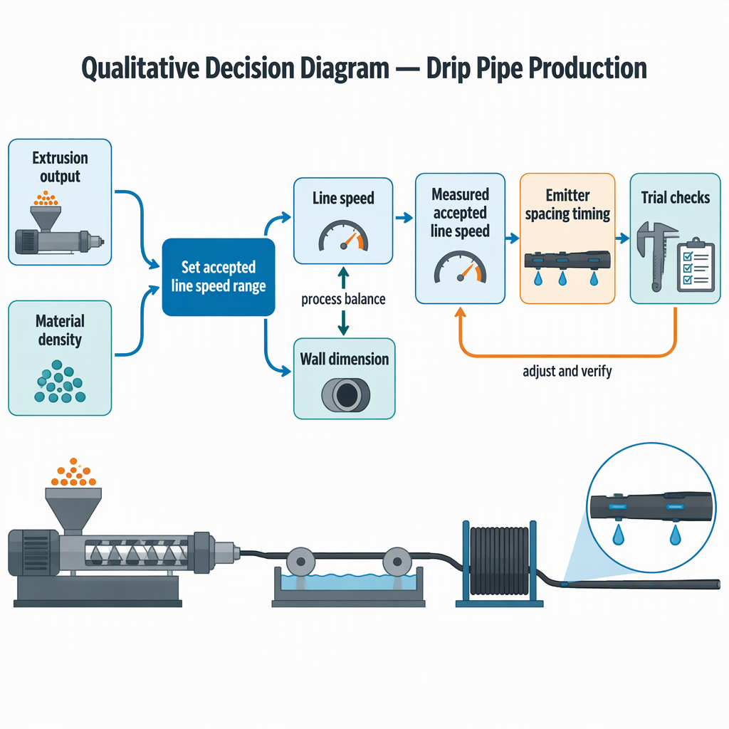
The useful starting relationship is mass balance: extrusion output is related to cross-sectional area, material density, and line speed. A manufacturing reference on extrusion output and line speed calculations describes this relationship for pipe, film, and profile extrusion.
| Speed change during a trial | Likely dimensional direction | Buyer check before accepting it |
|---|---|---|
| Speed is increased while output stays unchanged | Less material is available per metre, so wall and related dimensions may trend thinner after sizing and cooling. | Confirm outside diameter, wall thickness, ovality, cooling completion, and winding stability on accepted samples. |
| Speed is reduced while output stays unchanged | More material is available per metre, so wall and related dimensions may trend heavier unless output is reduced. | Check whether the product still meets the intended weight, coil handling, and downstream emitter process requirements. |
| Output and haul-off speed are changed together | Dimensions can be held closer to target when output, speed, sizing, and cooling are balanced. | Record the full setting set, not only the speed number, so the trial can be repeated. |
How line speed changes emitter spacing
Emitter spacing depends on how far the pipe or tape travels between repeated emitter insertion, punching, or indexing events, so the timing of those events must be synchronized with measured line speed.
For trial review, effective line speed can be measured as accepted extrusion length divided by elapsed minutes; a manufacturing reference on effective line speed distinguishes accepted speed from gross speed.
The spacing target itself is an irrigation-design decision. FAO drip irrigation guidance describes drip systems as small-diameter plastic pipes fitted with emitters and notes that emitter spacing varies by use, with different arrangements for individual plants and row crops.
| Decision point | If line speed changes | What to verify |
|---|---|---|
| Emitter insertion or placement | The control interval must match the new accepted length per minute. | Measure actual emitter-to-emitter distance on accepted samples across the coil. |
| Punching or outlet creation | The indexing distance changes if the line travels farther or less far between events. | Check hole position against the emitter body and the specified product layout. |
| Irrigation application | A plant-spacing or soil-wetting requirement may demand a different emitter pitch than another crop or soil condition. | Confirm the target spacing with the irrigation design before tuning the machine. |
Do not choose emitter spacing only because a line can run at a certain speed. FAO describes wetting patterns as dependent on discharge and soil type, so the agricultural application should set the spacing target before the line setting is finalized.
Inputs to collect before selecting a production speed
Before choosing haul-off speed, collect the variables that control material per metre, dimensional stability, and emitter-position accuracy; a speed number without those inputs is not a specification.
- Target pipe or tape geometry: outside diameter, wall thickness, tape shape, and acceptable dimensional tolerance for the product family.
- Material density and expected extrusion output, because line speed must be balanced with cross-sectional area and material flow.
- Accepted length and elapsed time measurement method, so the plant can compare usable speed instead of only gross line movement.
- Irrigation application: crop type, plant spacing, soil condition, and wetting requirement that drive the emitter-spacing target.
- Downstream synchronization points: emitter feeding, insertion or welding, punching, inspection, haul-off traction, and winding tension.
- Cooling and handling checks: product shape at haul-off, coil stability, and whether samples remain within dimension after cooling.
| Input you know | How it guides the first speed window |
|---|---|
| Output, density, and cross-section target | Use them to estimate whether a proposed speed can supply the required material per metre. |
| Emitter spacing required by the irrigation layout | Use it to set the downstream index distance and reject speeds that cannot hold placement consistently. |
| Accepted length per elapsed minute | Use it to compare trial settings on usable production rather than gross motion. |
Sample-run procedure for setting speed without locking in wrong dimensions
A practical trial should start from a calculated speed estimate, then qualify accepted length, dimensions, emitter spacing, cooling, and winding before the setting becomes a production recipe.
- Calculate a starting point from target cross-section, material density, expected output, and line speed rather than selecting speed alone.
- Run a short stabilized sample at the selected settings and record extruder output, haul-off speed display, cooling settings, emitter process settings, and winder conditions.
- Measure accepted length over elapsed minutes and separate it from gross length so rejected start-up or unstable material does not inflate the usable speed.
- Cut samples from the beginning, middle, and end of the accepted run and measure outside dimension, wall thickness, shape, and surface condition.
- Measure emitter-to-emitter spacing or punched outlet spacing on accepted product and compare it with the target index distance.
- Only qualify the setting after dimensions and properties are checked at the intended wall thickness and cooling condition.
- Keep the same measurement method between trials.
- Change one major variable at a time when possible.
- Save the accepted setting set: output, speed, vacuum or sizing condition, cooling, indexing, and winding.
- Repeat the check after normal stops, restarts, or resin-lot changes if those events affect stability.
Speed alone does not prove safe wall thickness or complete cooling. The trial should qualify the actual dimensions and properties at the intended wall thickness before regular production begins.
Supplier questions for a retrofit or new drip pipe line
When evaluating a retrofit or a new line, ask suppliers how the extrusion, cooling, emitter process, haul-off, and winding will be coordinated for your product family rather than asking only for a headline speed.
- Confirm whether the offered scope matches your product family, such as flat dripper tape, round dripper pipe, PE pipe, drip components, or related drip irrigation products.
- Ask how the supplier calculates the starting speed from output, material density, and target geometry.
- Ask how accepted speed will be measured during trials and how rejected material will be separated from usable output.
- Ask how target emitter spacing will be confirmed against the irrigation application, not only against machine timing.
- Ask which inspection points are included for dimension, spacing, cooling, and winding quality during acceptance.
- Ask for the trial recipe format you will receive after commissioning, including all dependent settings rather than the haul-off speed alone.
For powered equipment trials, cleaning, unclogging, or manual access, switch off and disconnect the relevant electrical power source before opening guards or reaching into any extrusion, haul-off, punching, insertion, or winding area. Follow only the access steps permitted in the specific machine manual and supplier training.
Conclusion
The right haul-off speed is the speed that keeps your target dimensions, accepted output, emitter spacing, cooling, and winding stable at the same time.
Start with the irrigation requirement, translate it into product geometry and emitter spacing, estimate the speed from material balance, and then prove the setting with accepted samples.
- Dimension control depends on output, density, cross-section, and line speed together.
- Spacing control depends on synchronizing downstream events with accepted line speed.
- Emitter spacing should serve the crop, soil, discharge, and lateral layout requirement.
FAQs
These questions help buyers turn drip pipe haul off speed from a sales number into a measurable production setting.
How do I measure actual line speed during a trial?
Measure accepted extrusion length and divide it by elapsed minutes. Keep gross length separate if part of the run is rejected or unstable.
Why should I avoid a universal recommended haul-off speed?
A universal number ignores output, material density, cross-section, cooling, and downstream synchronization, so it cannot predict your actual dimensions or usable output.
Does faster haul-off always make thinner pipe?
If output and density stay constant, faster line speed reduces material per metre, which can move wall and dimensional results thinner. If output, sizing, and cooling are changed at the same time, the final result must be checked by sample measurement.
Does line speed set emitter spacing by itself?
No. Line speed determines how much product passes per minute, but emitter insertion, punching, or indexing must be timed to that movement and then verified on accepted samples.
Who should decide the emitter-spacing target?
The target should come from the irrigation application. FAO guidance links emitter arrangements and wetting patterns to use conditions such as crop arrangement, soil type, and discharge.
What should I ask when upgrading an old line?
Ask how the supplier will measure accepted speed, hold dimensions, synchronize the emitter process, and prove the setting with trial samples instead of relying on a headline speed claim.
Can I use one trial result for every product size?
No. A trial result belongs to the tested geometry, output, material, cooling condition, and downstream setting set. A different size or spacing target needs its own confirmation.


